
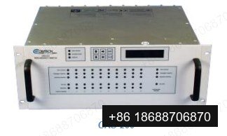
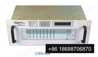
Comtech CRS 1:N Redundancy Switches for Legacy Modems
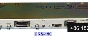
INTRODUCTION The C omtech EF Data 1:N Modem Redundancy Switches p rovide full protection of traffic circuits in the case of equipment failure. They are primarily intended for hub applications, and are compatible with a variety of Comtech EF Data Sate
Description
INTRODUCTION
The Comtech EF Data 1:N Modem Redundancy
Switches provide full protection of traffic circuits in the
case of equipment failure. They are primarily intended
for hub applications, and are compatible with a variety
of Comtech EF Data Satellite Modems. The protection
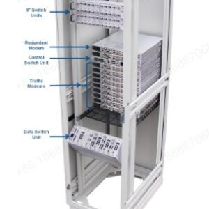
system consists of traffic modems (up to ten for the
CRS–200 and up to eight for the CRS–400), plus a
redundant modem, and a redundancy switch. An
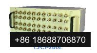
optional IF switch, CRS–280 or CRS–280L, is available
as a companion switch for multiple transponder or
multiple satellite applications.
COMPATIBILITY
These 1:N redundancy Switches support a wide–range
of terrestrial data interface types including: EIA –422,
V.35, EIA–232 and HSSI signals.
KEY RELIABILITY FEATURES
• Twin, independent AC supplies
• Passive back–plane for signal path
• Normal traffic is not interrupted upon power failure
• Non–interruption of user data when other traffic
modem Interface circuit cards are removed
• Data and clock are provided to the redundant modem
when in bridged mode
• Programmable holdoff times to backup or restore
• Audible alarm programmable to activate based on
various changes in status
• Provides single–point remote Monitor and Control
(M&C) to switch and traffic modems
• Simplified configuration and control
• 2 line x 24 character vacuum fluorescent display
• Front panel keypad
• LED system status display showing unit and modem
status, online/offline status and bridge status
SUPERIOR FUNCTIONALITY
The configuration of each traffic modem is stored in the
1:N controller. This information is used to program the
redundant modem if the traffic modem fails. The modem
information is copied to the controller through a serial
cable. The 1:N controller also controls the traffic and
redundant modem IF output. All modem outputs are ON
if the CRS–280/CRS–280L IF switch is used in the
system. The downlink path through the CRS–280/CRS–
280L is completely passive.
External monitor and control may be connected to the
CRS–230 controller board. The switch and each traffic
modem may be monitored or controlled through this
remote serial interface.
The data and clock signals to and from a traffic modems
are routed through a Traffic Modem Interface (TMI), via
a set of relays. This allows the data signals to pass
directly through to the traffic modem in the event of a
power failure. If the system’s power supplies are lost, or
if a TMI carrying traffic is removed, no interruption of
traffic takes place.
The bridge mode may be used to verify the user data on
a specific traffic modem. The redundant modem locks to
the traffic modem receive IF input signal. The operator
can program a delay interval for the backup modem to
wait before coming on line when a traffic modem failure
occurs.
MODULAR CONSTRUCTION
The redundancy switches are modular in construction.
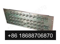
All replaceable modules insert into slots in the back
panel, including the controller, Traffic Modem Interfaces
(TMIs), Redundant Modem Interfaces (RMIs) and Power
Supply Units (PSUs). Power consumption is so low,
even for fully populated units, that no fan cooling is
required.
Additional information
| Weight | 11.3 kg |
|---|---|
| Dimensions | 36 × 48.26 × 18 cm |
| Brand | Comtech |
| Weight | 11.30 |
| Width | 48.26 |
| Height | 18.00 |
| Depth | 36.00 |
Reviews
There are no reviews yet.