
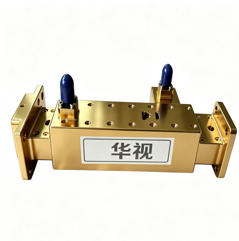
Directional Couplers 500MHz – 40GHz
CompareDescription
Product Overview
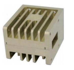
The HS-CP series directional couplers cover a broad frequency range from 500 MHz to 40 GHz, offering various coupling values (5/10/15/20/30/40 dB), connector options (SMA/N/2.92mm), and power handling (10W–100W) to meet the demands of RF test & measurement, communication systems, radar, and electronic warfare applications.
Featuring precision RF transmission-line structures and optimized coupling designs, the series delivers low insertion loss, high directivity, and excellent VSWR across wide bandwidths — making it an ideal choice for RF signal monitoring, power splitting, and system debugging.
Key Features
- Broadband Coverage: 500 MHz – 40 GHz (model-dependent segmentation)
- Multiple Coupling Values: 5 / 10 / 15 / 20 / 30 / 40 dB
- High Directivity: Typical 20–25 dB for superior main/aux isolation
- Low Insertion Loss: As low as 0.3 dB (low-frequency models)
- Excellent VSWR: ≤1.5 : 1 across the band
- Versatile RF Interfaces: SMA-F / N-F / 2.92mm-F
- High Power Handling: Up to 100W (N-connector models)
- Rugged aluminum housing with superior thermal dissipation
- Operating temperature -40°C to +85°C for harsh environments
- Typical Applications
- Satellite Communications (SatCom) — Uplink/downlink signal monitoring & power control
- Radar Systems — TX power sampling & echo signal coupling
- EW / SIGINT — Wideband signal interception & direction finding
- RF Test & Measurement — Spectrum analyzer / power meter signal sampling & calibration
- 5G / 6G Mobile Communications — Base-station PA output monitoring
- Research & Education — Microwave lab teaching & experimentation
- Model & Specifications
The table below lists key technical parameters for each HS-CP model. All specifications are measured at room temperature (+25°C).
| Model | Freq. (GHz) | IL (dB) | VSWR | Coupling (dB) | Direct. (dB) | Connector | Power (W) | Size (mm) |
| HS-CP112.5M/49S-10 | 0.05-1 | 1 | 1.3 | 10 | 22 | SMA-F | 10W | 30.4×26.4×10 |
| HS-CP1085M/270N-30 | 0.95-1.22 | 0.3 | 1.25 | 30 | 20 | N-F | 100W | 99×42×22.5 |
| HS-CP3G/2N-30 | 4.5-6.5 | 0.5 | 1.25 | 30 | 16 | Main: N-F / Aux: SMA-F | 50W | 69.14×61×21.3 |
| HS-CP2.15G/0.3S-20 | 2-2.3 | 1.5 | 1.3 | 20 | 15 | SMA-F | 10W | 66×29.5×13.44 |
| HS-CP2.35G/0.3N-5 | 2.2-2.5 | 0.5 | 1.3 | 5±0.3 | 15 | N-F | 20W | 55×21×18 |
| HS-CP4G/4N-20 | 4-8 | 0.4 | 1.3 | 20 | 20 | Main: N-F / Aux: SMA-F | 100W | 102.7×53.5×41.5 |
| HS-CP9G/6N-20 | 5-15 | 0.4 | 1.3 | 20 | 20 | Main: N-F / Aux: SMA-F | 100W | 62×47×35 |
| HS-CP12G/12N-40 | 5-17 | 0.7 | 1.25 | 40 | 15 | Main: N-F / Aux: SMA-F | 100W | 51.5×42×18 |
| HS-CP15.5G/19K-10 | 15.5-18 | 1.5 | 1.3 | 10±0.5 | 15 | 2.92mm-F | 10W | 34×17.55×9.85 |
| HS-CP13.5G/3S-15 | 13.5-16 | 0.6 | 1.25 | 15 | 25 | SMA-F | 20W | 130×35.8×24.8 |
| HS-CP24.5G/13K-20 | 18-31 | 1.5 | 1.3 | 20 | 15 | 2.92mm-F | 10W | 28×16×10 |
| HS-CP34G/12K-10 | 28-40 | 1 | 1.5 | 10 | 15 | 2.92mm-F | 10W | 130×35.8×24.8 |
Note: Some models use numeric frequency codes. Decoding rule: first 2–3 digits = integer part, last 3 digits = decimal part (in GHz). E.g., 45326 = 4.5–6.5 GHz; 45641 = 13.5–16 GHz.
General Specifications
The following parameters apply to the entire HS-CP product family unless otherwise noted:
| Parameter | Specification |
| Frequency Range | 500 MHz – 40 GHz (covered by various models) |
| Coupling Range | 5 – 40 dB (model dependent) |
| Directivity | ≥15 dB (typical 20–25 dB) |
| Insertion Loss | 0.3 – 1.5 dB (band dependent) |
| VSWR | ≤1.5 : 1 |
| Power Handling | 10W – 100W (model dependent) |
| Impedance | 50 Ω |
| Operating Temp. | -40 °C to +85 °C |
| Storage Temp. | -55 °C to +125 °C |
| Connector Type | SMA-F / N-F / 2.92mm-F (model dependent) |
| Housing Material | Aluminum alloy (conductive anodized) |
| Mounting | Screw / Flange mount |
| Compliance | RoHS / REACH |
Reviews
There are no reviews yet.