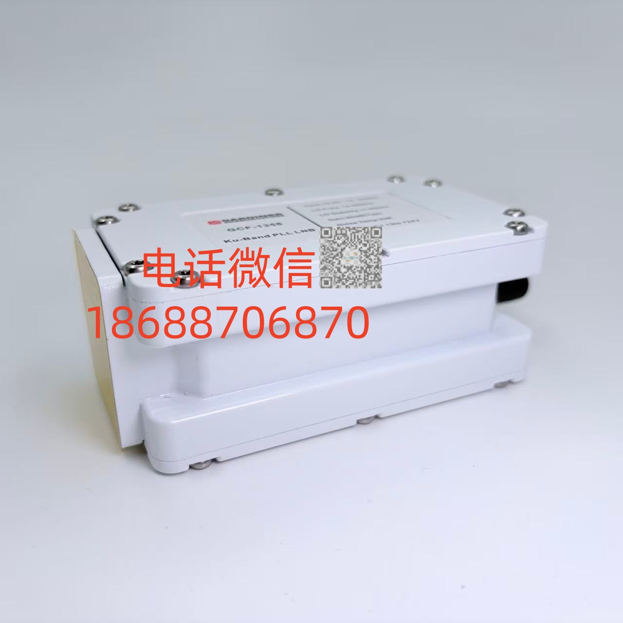
X Band LNB 7.90-8.50 GHz
CompareDescription
| Category | Item | Specification Parameters |
| Core Features | Extremely Low Noise Figure | Yes (specific values below) |
| Excellent Input VSWR | Max. 1.5:1, eliminates need for external isolator | |
| High P1dB & IP3 | Yes | |
| Low Phase Noise meeting DVB-S2X profile | Yes | |
| Wide Operating Temperature Range | -40 to +80°C | |
| Compact Size & Lightweight | Yes | |
| Product Description | Product Type | Professional X-Band PLL LNB with standard low phase noise, meeting DVB-S2X professional service requirements |
| Advantages | Extremely low input VSWR eliminating need for external isolator; standard 0 dB gain (typical) or customizable gain options available | |
| Frequency Range | 7.90 – 8.50 GHz | |
| Model | 6.95 | |
| LO Reference | Supports internal LO reference or external 10 MHz reference input; optional CPR 112G flange adapter | |
| Manufacturer | Swedish Microwave AB (commercial use) | |
| Connector Configuration | Input Waveguide | WR112 / R84, Flange PBR84 |
| Optional Pressurization | Max. 0.1 bar (optional) | |
| Maximum Input Power | 0 dBm (instantaneous, non-continuous) | |
| DC Input | +12 to +24 V supplied through output connector | |
| Operating Current | 190 mA @ +13 V 160 mA @ +15 V 140 mA @ +18 V 110 mA @ +24 V |
|
| Input VSWR | Max. 1.5:1 | |
| LO Reference | Internal or external 10 MHz reference (varies by model) | |
| External LO Reference Model | Sine wave, level -10 to +10 dBm, supplied through output connector; LO shifts -20 ppm without external 10 MHz signal | |
| Internal LO Reference Model | ±0.5 ppm (-20 to +70°C) ±1 ppm (-40 to +80°C) ±1 ppm (-20 to +70°C) ±1.5 ppm (-40 to +80°C) |
|
| LO Leakage | Max. -60 dBm (waveguide input) | |
| Internal Characteristics | Gain | Standard 0 dB (typical), customizable as required |
| Gain Flatness | ±0.4 dB within 30 MHz, max. ±2 dB across band | |
| Noise Figure | Max. 19.90 dB / 28000 K (at 0 dB gain) | |
| Phase Noise (Typical) | -35 dBc @ 10 Hz -65 dBc @ 100 Hz -85 dBc @ 1 kHz -90 dBc @ 10 kHz -100 dBc @ 100 kHz -128 dBc @ >1 MHz |
|
| Group Delay | Max. ±1 ns | |
| Out-of-Band Rejection | Min. 20 dB | |
| Image Rejection | Min. 60 dB | |
| Output Characteristics | IF Output Range | 950 – 1550 MHz |
| Output P1dB | Typical +5 dBm | |
| Output IP3 | Typical +15 dBm | |
| Output VSWR | Max. 1.7:1 @ 50 Ω | |
| Output Connector | N-type 50Ω, SMA-type 50Ω or F-type 75Ω | |
| General Characteristics | Dimensions | F-type & SMA-type connectors: 130 × 56 × 51 mm N-type connector: 135 × 56 × 51 mm |
| Weight | WR112: 353 g, CPR112G (F & SMA): 420 g WR112: 369 g, CPR112G (N): 446 g |
|
| MTBF | Per MIL-HDBK-217F Notice 2 standard: Ground Fixed (GF) environment: >489,000 hours Airborne Inhabited Cargo (AIC) environment: >245,000 hours Quality level: Commercial, calculation temperature: +35°C ambient |
|
| Operating & Storage Temperature Range | -40 to +80°C, -40 to +176°F | |
| Other | Enclosed conductive O-ring, mounting screws (M4 × 10) | |
| Optional Configurations | Separate SMA connector for DC input or external 10 MHz reference Customized gain CPR 112G flange adapter Extended IF |
Related products
-
Sale!
X-Band LNB 7.90–8.50 GHz
Original price was: ¥38,000.00.¥7,800.00Current price is: ¥7,800.00.
Reviews
There are no reviews yet.