
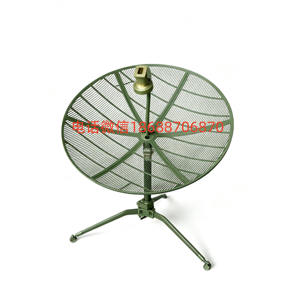
1.2m C-Band Carbon Fiber Antenna
CompareDescription
Product Overview
The Huashi HS120C is a high-performance 1.2-meter C-Band earth station antenna constructed from advanced carbon fiber composite materials. Designed for satellite communication applications, the HS120C delivers exceptional electrical performance, outstanding structural stability, and superior resistance to harsh environmental conditions.
The carbon fiber reflector achieves a surface accuracy of RMS ≤ 0.025 cm, ensuring optimal gain and low sidelobe performance across the full 3.7–4.2 GHz receive band. Its lightweight yet rigid construction makes it ideal for fixed earth stations, VSAT terminals, broadcast uplink/downlink, and emergency communication deployments.
■ Key Features
- Ultra-high surface accuracy (RMS ≤ 0.25 mm) for maximum aperture efficiency
- Carbon fiber composite reflector — lightweight, high stiffness, zero thermal deformation
- Full C-Band coverage: 3.7–4.2 GHz receive frequency range
- Gain ≥ 31.5 dBi across all frequencies (peak 32.33 dBi @ 4.0 GHz)
- Excellent sidelobe performance: first sidelobe ≤ -16.7 dB
- Superior wind resistance — operational in winds up to 25 m/s
- Wide operating temperature range: -40°C to +60°C
- Easy installation with modular design — single-person assembly possible
- Corrosion-resistant materials suitable for coastal and marine environments
- Compatible with all major satellite modem and RF equipment brands
■ Typical Applications
- Satellite News Gathering (SNG) and broadcast contribution
- VSAT networks and private communication networks
- Telemetry, Tracking & Command (TT&C) ground stations
- Disaster recovery and emergency communication systems
- Internet backbone and broadband access via satellite
- Defense and government secure communication links
■ Technical Specifications
Electrical Specifications
| Parameter | Specification | Test Condition |
| Frequency Range | 3.7 – 4.2 GHz | Receive |
| Polarization | Linear / Circular | Configurable |
| VSWR | ≤ 1.35:1 | Across full band |
| Feed Insertion Loss | ≤ 0.45 dB | C-Band |
| 3dB Beamwidth (Az) | 3.65° – 4.45° | See test data |
| 3dB Beamwidth (El) | 3.65° – 4.40° | See test data |
| First Sidelobe (Az) | ≤ -21.23 dB | Typical, varies w/ freq. |
| First Sidelobe (El) | ≤ -16.70 dB | Typical, varies w/ freq. |
| Gain (Peak) | 32.33 dBi | @ 4.0 GHz |
| Gain (Min.) | 31.57 dBi | @ 3.7 GHz |
| Gain Variation | ≤ 0.76 dB | Across 3.7–4.2 GHz |
Mechanical Specifications
| Parameter | Specification | Remarks |
| Reflector Diameter | 1.2 m | Prime focus |
| Reflector Material | Carbon Fiber Composite | CFRP |
| Surface Accuracy (RMS) | ≤ 0.025 cm | ≈ λ/60 @ 4.2 GHz |
| Antenna Weight | ≤ 18 kg (reflector only) | Excl. mount & feed |
| Total Weight (assembled) | ≤ 28 kg | Incl. mount & feed |
| Mount Type | Azimuth-Elevation (Az/El) | Manual / motorized opt. |
| Azimuth Range | 0° – 360° continuous | — |
| Elevation Range | 5° – 90° | — |
| Wind Load (operational) | ≤ 25 m/s | Survival: 40 m/s |
Environmental Specifications
| Parameter | Specification | Standard |
| Operating Temperature | -40°C to +60°C | IEC 60721-3-4 |
| Storage Temperature | -50°C to +70°C | — |
| Relative Humidity | 5% – 100% (non-condensing) | — |
| Ingress Protection | IP65 | IEC 60529 |
| Salt Fog Resistance | Class 4 (marine-grade) | IEC 60068-2-52 |
| UV Resistance | Excellent (carbon fiber intrinsic) | — |
■ Electrical Test Results
Test Method: 3dB / 10dB Beamwidth Method
Measurement Environment: Outdoor far-field range using spectrum analyzer
3dB & 10dB Beamwidth Results
| Freq (GHz) | 3dB Az (°) | 3dB El (°) | 10dB Az (°) | 10dB El (°) | Gain (dBi) | Sidelobe Az (dB) |
| 3.7 | 4.45 | 4.10 | 7.80 | 7.15 | 31.57 | -29.41 |
| 3.8 | 4.15 | 4.40 | 7.20 | 7.60 | 31.60 | -21.23 |
| 3.9 | 4.15 | 3.90 | 7.20 | 6.90 | 32.05 | -24.35 |
| 4.0 | 4.15 | 3.65 | 7.35 | 6.30 | 32.33 | -22.56 |
| 4.1 | 3.85 | 4.15 | 6.70 | 7.15 | 32.12 | -21.66 |
| 4.2 | 3.95 | 3.90 | 6.80 | 6.75 | 32.15 | -25.86 |
Gain Calculation Formula
| Formula | G = 10·log₁₀[(95,650·AZ₃·EL₃) / (AZ₁₀·EL₁₀)] – LF – LM |
| Where | AZ₃ = azimuth 3dB BW (°), EL₃ = elevation 3dB BW (°), AZ₁₀ = azimuth 10dB BW (°), EL₁₀ = elevation 10dB BW (°) |
| Feed Loss (LF) | 0.45 dB (C-Band) |
| Surface Error Loss (LM) | LM = 0.763 × (δ × F)² ; δ = 0.025 cm, F = freq in GHz |
First Sidelobe Level
| Freq (GHz) | Azimuth (dB) | Elevation (dB) | Worst Case (dB) |
| 3.7 | -29.41 | -17.04 | -17.04 |
| 3.8 | -21.23 | -18.08 | -18.08 |
| 3.9 | -24.35 | -21.63 | -21.63 |
| 4.0 | -22.56 | -16.70 | -16.70 |
| 4.1 | -21.66 | -20.84 | -20.84 |
| 4.2 | -25.86 | -18.74 | -18.74 |
■ Test Method & Conditions
Test Environment
| Test Method | Outdoor Far-Field (Spectrum Analyzer Method) |
| Reference Standard | 3dB / 10dB Beamwidth Method per industry standard |
| Test Frequencies | 3.7, 3.8, 3.9, 4.0, 4.1, 4.2 GHz |
| Signal Source | Unmodulated CW carrier from beacon antenna |
| Polarization Alignment | Transmitter & receiver polarizations matched |
| Test Object Count | 1 unit (serial-specific results) |
Test Procedure Summary
- Establish the C-Band polarization test system per the schematic diagram; power on and allow warm-up.
- Transmit an unmodulated single carrier at each test frequency (3.7–4.2 GHz).
- Rotate the AUT (Antenna Under Test) to align boresight with the beacon antenna; match polarization.
- Fix elevation; rotate azimuth from –θ° through boresight to +θ°; capture pattern on spectrum analyzer.
- Fix azimuth; rotate elevation from –θ° through boresight to +θ°; capture elevation pattern.
- Process data to extract 3dB / 10dB beamwidths and first sidelobe levels.
- Apply azimuth beamwidth correction for elevation angle; calculate gain using the standard formula.
■ Test Conclusion
✓ All electrical performance parameters meet or exceed the design specifications across the full 3.7–4.2 GHz operating band.
✓ Peak gain of 32.33 dBi achieved at 4.0 GHz; minimum gain of 31.57 dBi at 3.7 GHz — well within design margin.
✓ Gain variation across the band is only 0.76 dB, confirming excellent frequency stability.
✓ First sidelobe levels are consistently below -16.7 dB (elevation) and -21.2 dB (azimuth), demonstrating superior pattern purity.
✓ Carbon fiber reflector surface accuracy (RMS ≤ 0.025 cm) ensures minimal gain loss due to surface error.
✓ The HS120C antenna is certified fit for C-Band satellite communication applications.
Related products
-
-
Sale!
DCH-5300EC H.265/H.264 HD Live Encoder
Original price was: ¥10,800.00.¥5,800.00Current price is: ¥5,800.00. -
Sale!
DMM-2410EC-H 4路H.264 HD/SD、MPEG-2 SD Encoder Transcoder编码器 转码器
Original price was: ¥18,000.00.¥9,800.00Current price is: ¥9,800.00. -
Sale!

NJT8315 JRC Ku 4W 12.70-13.20GHz BUC 功放 2W
Original price was: ¥7,800.00.¥4,980.00Current price is: ¥4,980.00.
Reviews
There are no reviews yet.