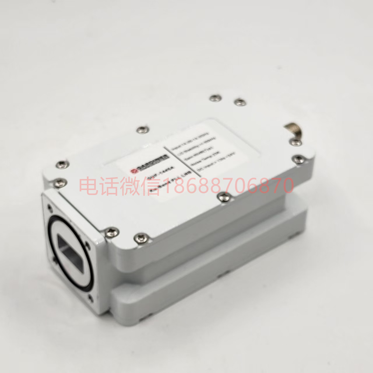
27.5-31GHz LNB 下变频器 低噪声放大器 降频器 KA Band LNB 高频头
GX2731E 27-31GHz 四本振低噪声放大器 LNB
| 项目 | Band 1 | Band 2 | Band 3 | Band 4 |
| 本振(LO)频率(GHz) | 26.05 | 27.05 | 28.05 | 29.05 |
| 输入(INPUT) | ||||
| 输入频率(GHz) | 27.00 – 28.50 | 28.00 – 29.50 | 29.00 – 30.50 | 30.00 – 31.00 |
| 波段切换 | 上述2 – 4个波段,通过13/18V和22 kHz音调或M&C(监控与控制)切换 | |||
| 输入波导(Input WG) | 波导WR28,法兰PBR 320 | |||
| 直流输入(DC Input) | 标称+12至+24 V,通过射频输出连接器或单独连接器(SMA)供电,功耗最大6W | |||
| 输入电压驻波比(Input VSWR) | 最大2.0:1 | |||
| 内部(INTERNAL) | ||||
| 本振参考(LO reference) | 外部10 MHz参考,故障时回退至内部参考(内部参考精度±30 ppm,温度范围 -40至+71°C) | |||
| 内部本振参考(Internal LO ref.) | 最大±30 ppm,温度范围 -40至+71°C | |||
| 外部10 MHz参考(External 10 MHz ref.) | 正弦波,电平 -10 dBm至+10 dBm,通过输出连接器或可选单独SMA连接器提供 | |||
| 本振泄漏(LO Leakage) | 波导输入时最大 -60 dBm,中频输出时最大 -40 dBm | |||
| 增益(Gain) | 典型40 dB,可通过M&C定制0 – 40 dB | |||
| 增益平坦度(Gain Flatness) | 30 MHz内最大±0.4 dB,每个波段内最大±2 dB(温度范围 -40至+71°C) | |||
| 增益稳定性(Gain Stability) | 24小时内最大±1 dB | |||
| 温度补偿(Temp. compensated) | 是 | |||
| 噪声系数(Noise figure @ 23°C) | 4.0 dB / 438 K | |||
| 相位噪声(Phase Noise) | 典型值: -34 dBc @ 10 Hz -64 dBc @ 100 Hz -84 dBc @ 1 kHz -92 dBc @ 10 kHz -96 dBc @ 100 kHz -113 dBc @ 1 MHz -123 dBc @ >10 MHz |
|||
| 群延迟(Group delay) | 最大±1 ns | |||
| 镜像抑制(Image Rejection) | 最小37 dB(本振 > 28.05时),最小27 dB(其他情况) | |||
| 输出(OUTPUT) | ||||
| 输出频率(MHz) | 950 – 2450 | 950 – 2450 | 950 – 2450 | 950 – 1950 |
| 输出1 dB压缩点(Output P1dB) | 最小+15 dBm | |||
| 输出三阶交调点(Output IP3) | 最小+25 dBm | |||
| 输出电压驻波比(Output VSWR) | 最大2.0:1 | |||
| 输出连接器(Output Connector) | N型母头50Ω或SMA型母头50Ω | |||
| 通用(GENERAL) | ||||
| 报警(Alarm) | 总和报警,通过M&C设置为以下任意组合报警: 高/低电流、本振锁定(外部/内部)、信号功率高/低、供电电压低/高。 开集电极3.3至28 V,最大200 mA(主机侧上拉10 kΩ),常开/常闭(NO/NC),M8连接器的引脚1 |
|||
| 监控与控制 | 通过MODBUS RTU RS485电气接口 注意!需与M8公头连接器/电缆匹配,仅使用屏蔽电缆(最低CAT5) |
|||
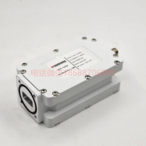
| 尺寸(Dimensions) | 144 x 74 x 44 mm(N型连接器) | |||
| 重量(Weight) | 455 g(N型连接器) | |||
Description
GX2731E 27-31GHz Quad LO Low Noise Amplifier LNB
| Item | Band 1 | Band 2 | Band 3 | Band 4 |
|---|---|---|---|---|
| Local Oscillator (LO) Frequency (GHz) | 26.05 | 27.05 | 28.05 | 29.05 |
| Input (INPUT) | ||||
| Input Frequency (GHz) | 27.00 – 28.50 | 28.00 – 29.50 | 29.00 – 30.50 | 30.00 – 31.00 |
| Band Switching | The above 2–4 bands are switched via 13/18V and 22 kHz tone or M&C (Monitoring & Control) | |||
| Input Waveguide (Input WG) | WR28 waveguide, PBR 320 flange | |||
| DC Input (DC Input) | Nominal +12 to +24 V, powered via RF output connector or separate connector (SMA), max power consumption 6W | |||
| Input VSWR (Input Voltage Standing Wave Ratio) | Max 2.0:1 | |||
| Internal (INTERNAL) | ||||
| LO Reference (LO reference) | External 10 MHz reference, falls back to internal reference in case of failure (internal reference accuracy ±30 ppm, temperature range –40 to +71°C) | |||
| Internal LO Reference (Internal LO ref.) | Max ±30 ppm, temperature range –40 to +71°C | |||
| External 10 MHz Reference (External 10 MHz ref.) | Sine wave, level –10 dBm to +10 dBm, provided via output connector or optional separate SMA connector | |||
| LO Leakage (LO Leakage) | Max –60 dBm at waveguide input, max –40 dBm at IF output | |||
| Gain (Gain) | Typ. 40 dB, customizable 0 – 40 dB via M&C | |||
| Gain Flatness (Gain Flatness) | Max ±0.4 dB within 30 MHz, max ±2 dB within each band (temperature range –40 to +71°C) | |||
| Gain Stability (Gain Stability) | Max ±1 dB within 24 hours | |||
| Temperature Compensated (Temp. compensated) | Yes | |||
| Noise Figure (@ 23°C) (Noise figure @ 23°C) | 4.0 dB / 438 K | |||
| Phase Noise (Phase Noise) | Typical values: –34 dBc @ 10 Hz –64 dBc @ 100 Hz –84 dBc @ 1 kHz –92 dBc @ 10 kHz –96 dBc @ 100 kHz –113 dBc @ 1 MHz –123 dBc @ >10 MHz |
|||
| Group Delay (Group delay) | Max ±1 ns | |||
| Image Rejection (Image Rejection) | Min 37 dB (when LO > 28.05), min 27 dB (otherwise) | |||
| Output (OUTPUT) | ||||
| Output Frequency (MHz) | 950 – 2450 | 950 – 2450 | 950 – 2450 | 950 – 1950 |
| Output 1 dB Compression Point (Output P1dB) | Min +15 dBm | |||
| Output Third Order Intercept (Output IP3) | Min +25 dBm | |||
| Output VSWR (Output Voltage Standing Wave Ratio) | Max 2.0:1 | |||
| Output Connector (Output Connector) | N-type female 50Ω or SMA-type female 50Ω | |||
| General (GENERAL) | ||||
| Alarm (Alarm) | Summary alarm, configurable via M&C for any combination of the following: High/Low current, LO lock (external/internal), signal power high/low, supply voltage low/high. Open collector 3.3 to 28 V, max 200 mA (host-side pull-up 10 kΩ), normally open / normally closed (NO/NC), pin 1 of M8 connector |
|||
| Monitoring & Control (Monitoring & Control) | Via MODBUS RTU RS485 electrical interface | |||
| Note: Must be used with M8 male connector/cable, shielded cable only (minimum CAT5) | ||||
| Dimensions (Dimensions) | 144 x 74 x 44 mm (N-type connector) | |||
| Weight (Weight) | 455 g (N-type connector) |
Tel:+86 18688706870 E-mail:szwisi88@qq.com
Reviews
There are no reviews yet.